Instead of the default SMT footprint on the main board, the system can be upgraded with a separate CPU upgrade module. The benefit of having the processor on a separate module is, it removes the risk of losing an entire Z20X main board in case the soldering of that single SMT part didn’t go according to plan. The additional benefit is the inherent flexibility of having different type of processor modules using the same system resources.
The processor module is optional and only required in systems where the eZ80 processor is not installed directly on board.
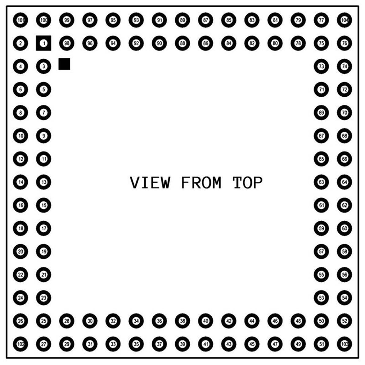
The CPU module pinout follows strictly the eZ80’s pinout for the pins 1 through 100, with one notable exception. The RESET# pin (51) of eZ80 is held permanently low by the module since its pin 51 is connected to ground. Instead, the actual RESET# signal is fed to pin 103 of the module. Hence when the module is installed on the main board it will keep the on-board eZ80 in a permanent reset state, thus taking over completely the system bus.
The CPU module also has an additional provision of +5V power coming to pin 102.
Four pins are connected to external signals with 5V logic (PS/2 interface).
In order to maintain compatibility with the rest of the system, a CPU module that uses a different processor (not eZ80F92/93), should emulate the same pinout and functionality on all pins.
|
|
1 • A0 2 • A1 3 • A2 4 • A3 5 • A4 6 • A5 7 • +3.3V 8 • GND 9 • A6 10 • A7 11 • A8 12 • A9 13 • A10 14 • A11 15 • A12 16 • A13 17 • A14 18 • +3.3V 19 • GND 20 • A15 21 • A16 22 • A17 23 • A18 24 • A19 25 • A20 26 • A21 27 • A22 28 • A23 29 • CS0# 30 • CS1# 31 • CS2# 32 • CS3# 33 • +3.3V 34 • GND 35 • D0 36 • D1 37 • D2 38 • D3 39 • D4 40 • D5 41 • D6 42 • D7 43 • +3.3V 44 • GND 45 • IO# 46 • MEM# 47 • RD# 48 • WR# 49 • INSTR# 50 • WAIT# 51 • GND 52 • NMI# |
53 • BUSREQ# 54 • BUSACK# 55 • HALT# 56 • +3.3V 57 • GND 58 • RTCI_32768 59 • RTCO_32768 60 • +3.3V_RTC 61 • GND 62 • TMS 63 • TCK (ZCL) 64 • TRIGOUT 65 • TDI (ZDA) 66 • TDO 67 • +3.3V 68 • PD0/TxD0 69 • PD1/RxD0 70 • PD2/RTS0# 71 • PD3/CTS0# 72 • PD4/DTR0# 73 • PD5/DSR0# 74 • PD6/DCD0# 75 • PD7/RI0# 76 • PC0/TxD1 77 • PC1/RxD1 78 • BACKLIGHT 79 • TOUCH_IRQ# 80 • PS2MD (5V) 81 • PS2MC (5V) 82 • PS2KD (5V) 83 • PS2KC (5V) 84 • GND 85 • XT1_18MHZ 86 • XTO_18MHZ 87 • +3.3V 88 • PB0/T0IN 89 • TOUCH# 90 • PB2 91 • SCLK 92 • SD# 93 • PB5 (FLASH#) 94 • MISO 95 • MOSI 96 • +3.3V 97 • GND 98 • SDA 99 • SCL 100 • FREQ_CPU 101 • unused 102 • +5V 103 • RESET# 104 • unused |